Home
/
All Products
/
Thermal Management
/
Heat Sinks
/
Board Level Heat Sinks
/
Stamped Heat Sinks
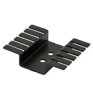
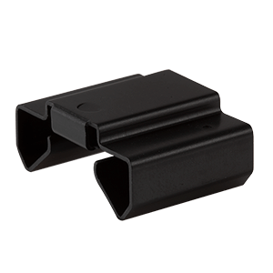
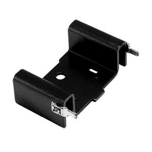
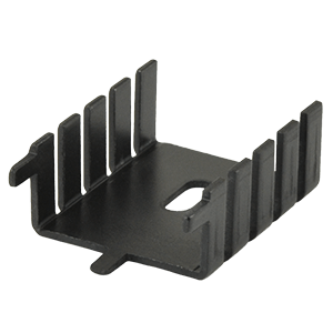
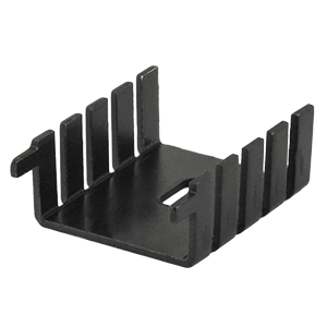
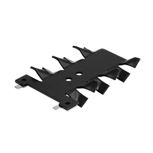
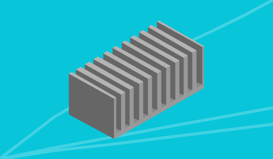
Stamped Heat Sinks
Ideal for lower power PCB cooling, CUI Devices’ stamped heat sinks are made from aluminum or copper with black anodized or tin-plated material finishes. Supporting a variety of transistor packages, our stampings are available in sizes from 8 to 50.8 mm with heights from 4 to 25.4 mm. Our stamped heat sinks are measured under four conditions for thermal resistance and carry power dissipation ratings from 2.1 up to 10.29 W at 75°C.
Package Cooled
TO-218
TO-220
TO-252
TO-263
Reset
Mounting Style
PCB
Surface Mount
Reset
Solder Pin Orientation
Horizontal
No Pin
Vertical
Reset
Solder Pin Length (mm)
Min
Max
GO
2.54
2.74
2.8
3.18
3.2
3.8
3.9
4
4.3
4.31
5
5.03
5.08
5.1
5.3
6.1
6.35
6.5
7.4
8.26
8.5
9.5
9.53
9.7
Reset
Rth @ 75°C ΔT, nat conv (°C/W)
Min
Max
GO
7.29
7.59
7.65
9.56
10.14
10.19
10.9
11.03
11.54
12.75
12.79
13.67
14.71
15.16
15.5
15.79
15.83
16.3
16.66
17.05
17.74
18.12
18.29
18.34
18.63
18.82
19.22
19.74
20.59
20.83
20.93
22.06
22.39
23.9
24.79
25.35
25.86
25.92
26.13
26.32
26.4
27.37
27.66
27.78
28.85
29.09
29.57
32.69
33.28
35.71
Reset
Rth @ 1 W, nat conv (°C/W)
Min
Max
GO
9.28
9.7
10.6
12.5
12.99
13.4
14.1
14.33
15.27
15.8
16.2
16.9
18.6
18.99
19.1
19.73
19.8
20
20.24
20.27
20.74
21.9
21.92
22.14
22.47
22.64
22.9
23.05
23.32
24.3
24.62
26.05
26.6
27.22
28.6
29.7
30.28
30.4
30.86
31.07
31.2
31.94
32.65
32.7
32.8
33.89
33.93
35.46
35.5
37.62
39.9
40.16
41.98
Reset
Rth @ 1 W, 200 LFM (°C/W)
Min
Max
GO
2.01
3.47
3.5
3.51
3.7
3.76
4.2
4.3
4.51
4.8
5
5.01
5.39
5.44
5.5
5.6
5.72
5.83
5.87
5.88
6.3
6.32
6.5
6.86
6.9
7.05
7.24
7.45
7.46
7.51
7.7
7.9
8.15
8.18
8.5
8.8
9.2
9.51
10.05
10.1
10.49
10.6
10.68
10.9
11.04
11.2
11.6
12
12.6
13.2
14
Reset
Rth @ 1 W, 400 LFM (°C/W)
Min
Max
GO
1.71
2.42
2.74
2.9
2.98
3
3.1
3.2
3.4
3.7
4
4.01
4.1
4.17
4.22
4.48
4.5
4.51
4.58
4.85
5.08
5.2
5.56
5.7
5.76
5.8
5.84
5.9
6.09
6.1
6.2
6.25
6.5
6.53
6.7
6.81
6.84
7.3
7.5
7.87
7.88
8.1
8.48
8.5
8.6
8.9
9
10.3
Reset
PD @ 75°C ΔT, nat conv (W)
Min
Max
GO
2.1
2.25
2.29
2.54
2.58
2.6
2.7
2.71
2.74
2.84
2.85
2.87
2.89
2.9
2.96
3.03
3.14
3.35
3.4
3.58
3.6
3.64
3.8
3.9
3.98
4.02
4.09
4.1
4.14
4.23
4.4
4.5
4.6
4.74
4.75
4.76
4.84
4.95
5.1
5.49
5.86
5.88
6.5
6.8
6.88
7.36
7.4
7.85
9.8
9.89
10.29
Reset
Length (mm)
Min
Max
GO
8
12.7
14.99
15
17.78
18.79
19
19.05
19.38
20
21.66
23.4
23.62
24.4
25.4
27.96
29.97
30
30.3
31
31.8
36.83
38
38.1
41
41.66
41.91
42.5
44.45
49.31
50.8
Reset
Width (mm)
Min
Max
GO
12.8
13
13.21
17.8
19
19.7
19.8
20
21.1
22
22.2
22.86
24.9
25
25.25
25.4
25.91
26.2
32
33.02
35
38.1
42
44.45
48.26
51
Reset
Height (mm)
Min
Max
GO
4
5.35
6.35
7.1
7.7
8.5
9.4
9.5
9.52
9.53
9.65
9.91
10
10.16
11
11.2
11.43
11.94
12.5
12.7
12.9
13.08
18.5
19
20
21.59
24.13
25
25.4
Reset
Material
AL1050
AL1100
AL5052
C1100
Reset
Material Finish
Black Anodized
Tin Plated
Reset
Series
HSS-B20-01
HSS-B20-02
HSS-B20-04
HSS-B20-05
HSS-B20-0508H
HSS-B20-0635
HSS-B20-07
HSS-B20-NPX-01
HSS-B20-NPX-02
Reset
Rth = Thermal Resistance, PD = Power Dissipation

Resources
Here to assist you at every stage of the design journey.