All You Need to Know About Electret Condenser Microphones

In the realm of audio technology, electret condenser microphones (ECMs) stand as a tried-and-true component for sound capture and versatility in various applications. Although their MEMS microphone counterparts have taken much of the recent spotlight, ECMs still find plenty of uses in designs due to their flexible mounting styles, directionality options, and more. In this blog post, we will uncover how ECMs work, their directional capabilities, and key specifications. From omnidirectional microphones capturing ambient sound to unidirectional variants focusing on specific sources, we will discuss best practices for selection and mounting of ECMs to ensure optimal performance across various settings.
Shop CUI Devices’ range of electret condenser microphones and MEMS microphones or further explore their differences in our blog post or video comparing the two technologies.
What are Electret Condenser Microphones?
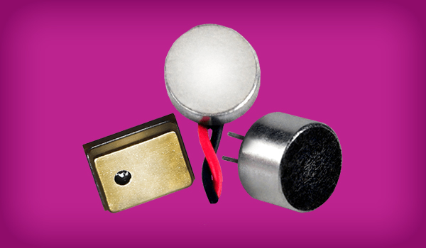
Electret condenser microphones (ECM), also called capacitor microphones, utilize an electret, which is a ferroelectric material that has been permanently electrically charged or polarized. Due to the high resistance and chemical stability of the material, the electrical charge will not decay for hundreds of years. The name comes from “electrostatic and magnet”; a static charge is embedded in an electret by alignment of the static charges in the material, much the way a magnet is made by aligning the magnetic domains in a piece of iron. This specific characteristic is a benefit to designers because an electret condenser microphone eliminates the need for a polarizing voltage to operate the microphone.
How Do Electret Condenser Microphones Work?
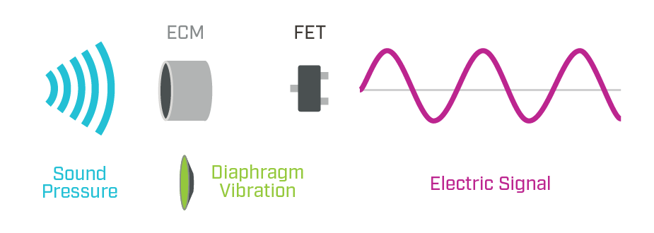
The working principle of an electret condenser microphone is that the diaphragm acts as one plate of a capacitor. Vibrations produce changes in the distance between the diaphragm and the back plate. The voltage maintained across the diaphragm and the back plate changes with the vibrations in the air, according to the capacitance equation:
C = Q / V
Where:
- Q = charge in coulombs
- C = capacitance in farads
- V = potential difference in volts
This change in voltage is amplified by the FET and the audio signal appears at the output, after a dc-blocking capacitor.
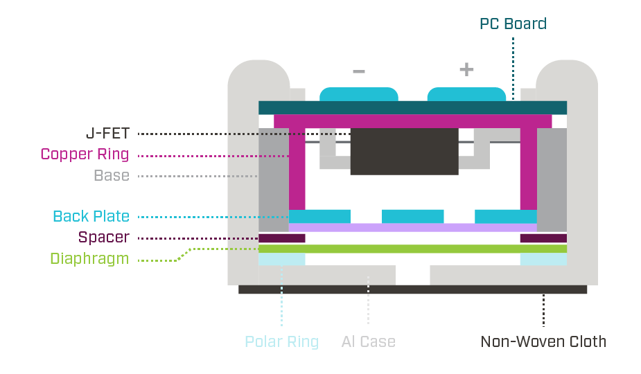
Outside of its basic operation, the typical structure of an electret condenser microphone is composed of a non-woven cloth, a case, a polar ring, a diaphragm, a spacer, a back plate, a base, a copper ring, and a printed circuit board (PCB). The electret material is applied to the diaphragm and shown as the polar ring. Shown here is an illustration that highlights ECM structure and breaks down the individual components of a typical ECM.
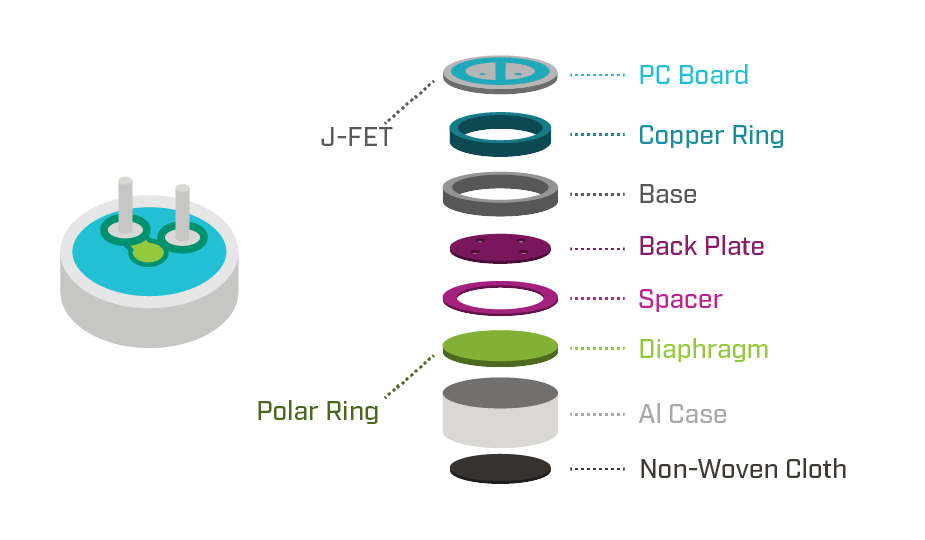
The illustration shown here highlights the structure of a typical electret condenser microphone after all the components have been assembled.
Microphone Directionality or Polar Patterns
Electret condenser microphones are available in several directionality or polar patterns, which define how a microphone picks up sounds from different directions. Microphone directionality is a crucial specification to understand and will be determined by your specific application and usage requirements. The most common ECM directionality types available are omnidirectional, unidirectional, and noise cancelling, which will now each be explained in greater detail.
Omnidirectional Microphones
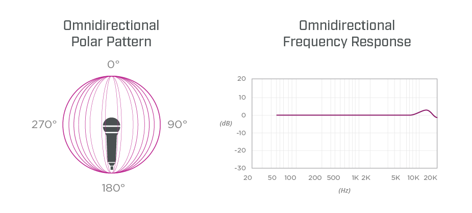
Omnidirectional microphones are designed to receive vibrations from virtually any direction. The diagram in each of the following sections shows the pattern of how the microphone receives sound. The microphone faces upward (toward the viewer) and sound intensity for a particular frequency is plotted for angles radially from 0° to 360°, with 0° representing the front of the microphone. Because these microphones can pick up sound from any direction, they are often used to record a group of vocalists, or for meetings such as conference calls. However, omnidirectional microphones do have some drawbacks. As the microphone cannot discriminate between wanted and unwanted sounds, ambient noise from the environment can be picked up and amplified.
Unidirectional Microphones
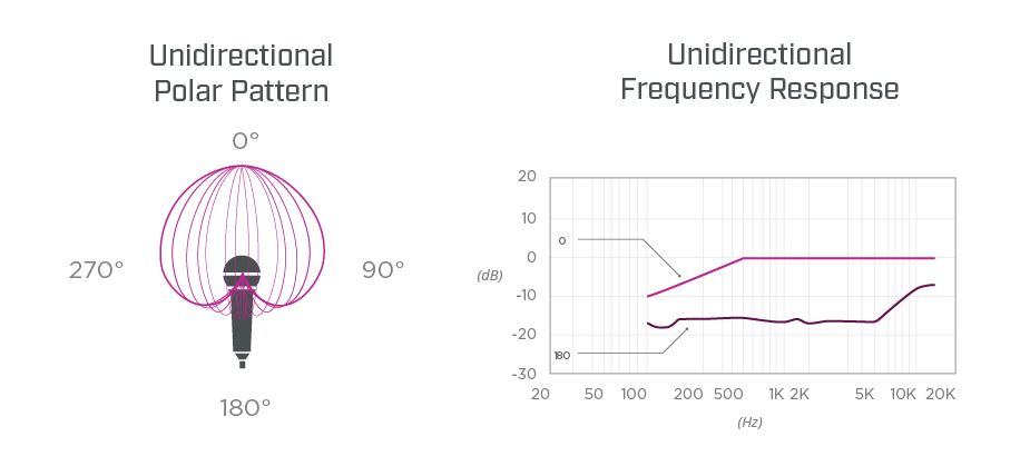
Unidirectional microphones are sensitive to sounds primarily from one direction and eliminate unwanted background noises, such as chatter, keyboard, or paper sounds. Microphones with this type of pattern are commonly used as vocal or speech microphones, since they are good at rejecting sounds from directions other than the desired location. The diagram below depicts the most common unidirectional pattern, which has wide pickup and maximum rejection at 180° off-axis.
Noise Cancelling Frequency Response
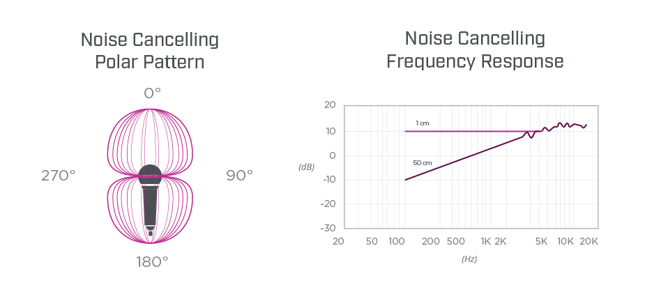
A noise canceling microphone, also known as a bidirectional microphone, is designed to filter out ambient noise from a desired sound or direction. These are particularly useful in noisy environments. All noise cancelling microphones have at least two ports through which sound enters. The front port is normally oriented toward the desired sound and another port is oriented at a sound that is more distant. Sound that is much closer to the front port than to the rear will make more of a pressure gradient between the front and back of the diaphragm, causing it to move more. The microphone's proximity effect is adjusted so that flat frequency response is achieved for sound sources very close to the front of the microphone. Sounds arriving from other angles are subject to steep midrange and bass roll-off. Bidirectional noise cancelling microphones can be found in call centers, helicopters, and race car driver headsets.
Key Electret Condenser Microphone Specifications
- Directivity: A microphone’s directionality or polar pattern indicates how sensitive it is to sounds arriving at different angles about its central axis.
- Sensitivity Reduction: The amount of gain that a microphone will lose if the voltage powering the microphone is decreased.
- Sensitivity: A microphone’s sensitivity measures how well a microphone picks up sound. A more sensitive microphone can detect quieter sounds or sounds from further away more easily, producing a stronger signal. Less sensitive microphones need more amplification to capture the same sound level, which can add noise. This characteristic helps determine the best microphone for different uses, like recording music or capturing audio in noisy environments.
- Signal to Noise Ratio (SNR): A ratio measuring the level of a desired signal (such as speech, music, etc.) that a microphone records compared to the level of noise that it picks up from the background.
Electret Condenser Microphone Mounting Considerations
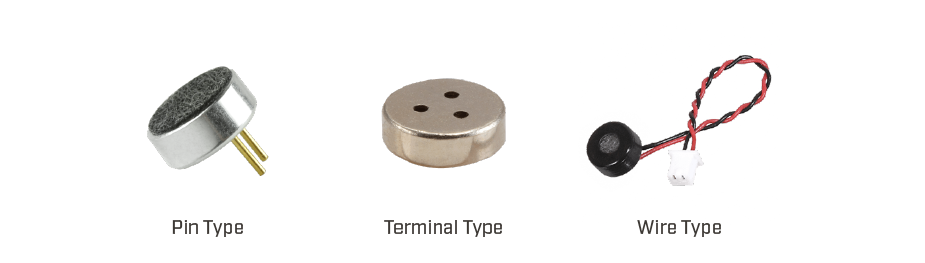
ECMs are available in various mounting configurations depending on the application requirement, including PCB pin, wire leads with or without a connector, and terminal types. Terminal types can be further categorized as being surface mount for reflow solder compatibility or having solder pads for hand soldering.
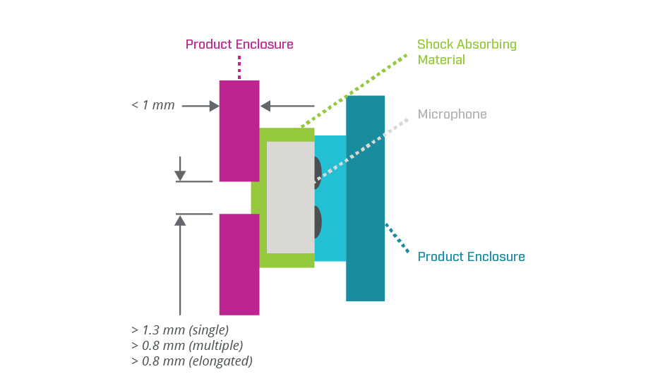
When mounting an electret condenser microphone, the microphone should be mechanically isolated from the product enclosure, so sound and vibrations are not transferred from the enclosure to the microphone and to ensure the microphone only receives sounds from the front holes of the enclosure. The thickness of the enclosure in front of the microphone should be less than 1 mm, while the holes in front of the microphone should have a diameter greater than 1.3 mm for a single hole or greater than 0.8 mm for multiple holes. Elongated holes should have a width greater than 0.8 mm.
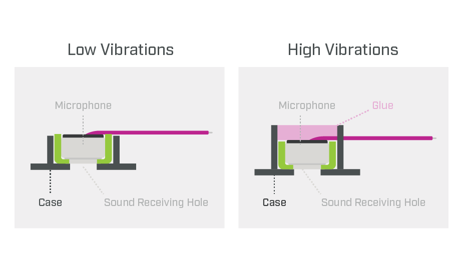
For low vibration applications the microphone can be mounted by friction fit or glued into a sleeve, while for high vibration applications the mounting sleeve should be extended, so glue can also be applied to the back of the microphone and the sleeve.
Conclusion
Electret condenser microphones still remain as indispensable tools in modern audio technology. Their ability to capture sound with precision and clarity, coupled with versatile directional capabilities, makes them essential in a wide range of applications. By understanding how ECMs work and their key specifications, users can make informed decisions when selecting the right microphone for their needs. CUI Devices’ full range of microphones as well as our audio design services are also here to help!
 Tags:
Tags:
Additional Resources